The movement of the microscope is achieved by four motors that control the position of the objective. The motors can be independent or coupled, depending on the operating mode selected in the Position panel in the Scanbox GUI.
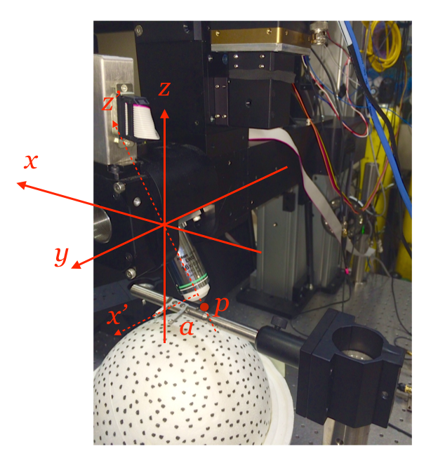
There are three positioning modes: normal, rotated and pivot. To explain how these work, we need to define the coordinate system used first. So, imagine yourself standing behind the main vertical holding post of the microscope arm.
In the normal mode, moving along the positive x-axis will move the objective to the right; movement along the positive y-axis will move the objective away from you; moving along the positive z-axis will move the objective up. There is a fourth degree of freedom that comes from the ability to rotate the objective in the (x,z) plane. The angle between the objective and the negative z-axis is defined as a. In the normal mode all these motors are independent of each other. Manipulating each of the controls only changes the axis selected.
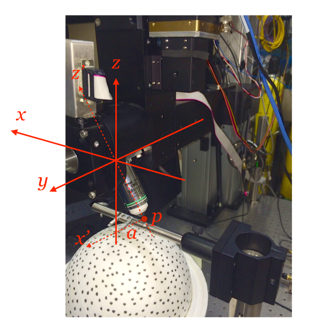
In the rotated mode, the x and z controls move the microscope along the x’ and z’ axes, which is obtained by rotating the (x,z) plane by a degrees. The z’ axis is along the line of sight of the objective and x’ is normal to it. In rotated mode, changing position of the x control will move the objective parallel to the x’ axis. In this mode the x and z motors are coupled so that the resulting movement is restricted to the plane normal to the objective. When changing the z control, movement will be along the z’ axis.
Finally, in the pivot move, movement of the x control will be coupled to that of z and the objective angle such that the focus point p remains under focus. To use this mode a quick calibration is required to measure the length between the focal point and the rotation axis of the objective. To do this set your objective to be in the vertical position and zero the position counters. Image some beads at a magnification of x1 and pick one near the center of the screen. Set the mode to normal, place your mouse cursor on top of the bead, and move the it to the left or right using the ShuttleExpress wheel. Now, switch to the a-axis and move the bead back to its original position by rotating the objective. When the bead is in its original position you can read out the movement in the x-axis (in um) and the a-axis (in deg). The ratio of these two numbers, in deg/um, defines the value of ‘pivotk’ in the sbconfig structure. In our system, we have sbconfig.pivotk = 5.9e-4 [deg/um].
