Update[6/1/2018]: Please update Scanbox to make this feature work correctly. An error in the code of earlier versions incorrectly set the gain for fixed-type amplifiers (variable type amplifiers were handled correctly). An alternative, easy way to fix the issue without having to update Scanbox is to search for the constant INPUT_RANGE_PM_1V in scanbox.m and replace it with INPUT_RANGE_PM_1_V (not the underscore between the 1 and the V). There is only one instance.
You may have one of two different PMT amplifiers in your setup. One which has a variable gain.

The typical settings of this amplifier should be: left the switch on GND, middle switch on H and with the knob set to a gain of 10^4, next switch on FBW and DC for the rightmost switch.
With Scanbox closed, launch the Alazar DSO application and set to Voltmeter View (View->Voltmeter in the menu bar). Then adjust the output with the offset screw on the left (do not confuse with the bias screw!) so that the reading is around 190mV.

Finally, edit the scanbox_config file and set pmt_amp_type to ‘variable’.
Alternatively, you may have a fixed gain amplifier that is a bit smaller and looks like this.
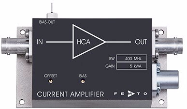
Here the gain is fixed (your version will read 5 x 10^4 V/A and 100MHz bandwidth). Follow the same instructions above to set the bias to 950mV by means of the offset screw. Then, make sure the pmt_amp_type is set to ‘fixed’ in the configuration file.
That’s all. These settings will allow you to maximize the dynamic range of your digitizer card and the contrast of the images.
Note: the pmt_amp_type variable is only present in the latest release of the software. So you will need to update to use this feature.

Our system has two different PMT amplifiers, one variable and one fixed. PMT0 (green channel) is the variable one. What setting should we use in the config file, variable or fixed?
Hmmm… Did not think about that possibility. Follow whatever the green channel is. I will give you the chance to define channels separately in the next version.