It is desirable to have an additional safety mechanism to prevent the scope from accidentally moving beyond a certain limit, such as imposing a lower limit on the z-axis beyond which the objective might hit an object.
The firmware on the motor box can be set up so an external signal coming from a limit switch causes all motors to stop and the system to quit.
To install such a limit switch you will have to open the motor box to have access to I/0 Connector 0 on the Trinamic 6110 board. This is the connector on the top left in this figure:

The following housing/connectors will be required to connect to it. You can get it here.

The pin-out of this connector looks as follows:
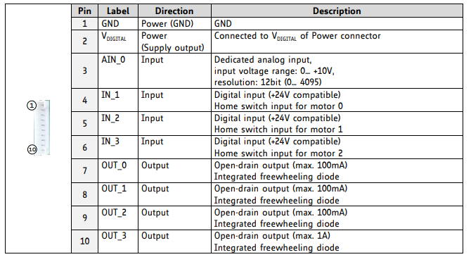
You will only need access to pin #1 (GND), pin #2 (V_digital) and pin #4 (IN_1).
Select a limit switch (3A/250V) with both normally open (NO) and normally closed (NC) pins in addition to the common input (COM). Connect NO to pin #2 (V_digital), NC to pin #1 (GND) and COM to pin #4 (IN_1). Alternatively, a simpler limit switch with a just a NO and GND pins will also work, as the IN_1 has a pull-down resistor.
The firmware version that enables the limit switch to trigger a panic interrupt is named scanknob_v4.tmc. Use the TMCL-IDE installed on the computer to open the file, compile it and download to the motor controller card.
To test the functionality of the switch, open Scanbox and while moving the scope with knobby, manually close the switch. All motors should then stop immediately and a window will pop up displaying a panic message:
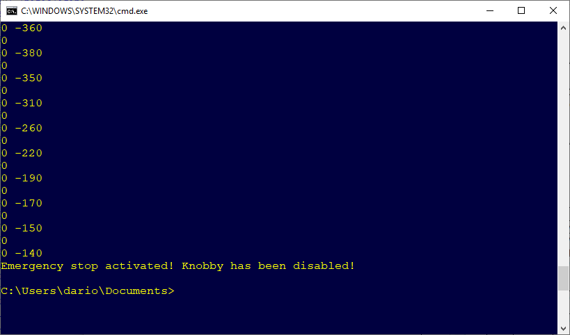
At this point the motor box and knobby are completely disabled. A full restart of Scanbox, after resolving the issue, will be required.
Finally, position the limit switch in the desired location before starting an imaging session.
Another use of this switch is as a simple emergency button. You can position it in a convenient place where you can press it if there is a need for an emergency stop.
